Here's the loop hung from the ceiling with string.
The feed is at top, capacitors bottom center.
 I've had an interest both in compact loops and in in-room hotel antennas for a while, but really hadn't gotten far. So I finally got around to trying a multi-turn design by Rod Newkirk, W9BRD in the July 1993 QST article called, "Honey, I Shrunk the Antenna". (Guess what movie was new at the time.) According to the author, the multi-turn design raises radiation resistance significantly, and a resonating capacitor in each turn, along with the multi-turn design, calms down the extremes of voltage and current seen in single turn loops.
The antenna is a rectangle 4.5 feet by 3.5 feet, three turns, each turn cut at the bottom (one 4.5 foot side) with a 40 pF capacitor inserted, one of them variable, and fed at the center of the opposite side, which is the top in my case.
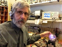
I used #14 AWG THWN house wire, stranded (it's a little springy). I made a little circuit board for inserting the three capacitors and another one for the feed line connection "insulator" at the top. Instead of etching, I just scored traces with my Dremel tool abrasive wheel. I mounted the variable capacitor on the opposite side of the (singled sided) board, using nylon screws so's not so short anything out. The capacitor is a dual section, unequal values (80 pF and 150 pF or so) in series. This is standard practice so current doesn't have to flow through the shaft to frame bearings. In the photo below, the variable cap is on the back side and connected to the center traces.

Circuit board material for series capacitor connections
The wire generally is bunched up, even tie-wrapped or taped in a few places, in keeping with how the author did it. In fact, he used a couple turns of 2/c zip cord and spared one pass of the resulting four.
The article called for 40 pF capacitors with the variable used for fine tuning. I put two 20.5 pF silver micas in parallel to get 41 pF with lower current in each. In the photo, I'm experimenting with just one capacitor. I'm publishing this a little prematurely as I'm still not satisfied with my values and possibly the quality of the capacitors. I got the SWR down to a fairly stable 2:1 and let the K3's ATU finish the job. I actually made two QSOs at 5 watts with the top of the antenna barely above head height. Note that my shack is on the ground floor.
More to come, maybe, if I make some improvements.
Nick, WA5BDU
August 4, 2009
1 comment:
Thanks for this report on your antenna experiment. I've been looking at similar things and will definitely be giving this one a try. I'll post it to my blog after I get it going and maybe we can compare notes in the future! 73, Kelly K4UPG
http://k4upg.com
Post a Comment