This started when I read a user's group post by Rick Campbell KK7B about these Collins VFOs that were at least at one time easily available from hamfests at low prices. And furthermore, they could be converted from tube operation to solid state without much difficulty. The advantages are low drift and low phase noise, among other things.
So I started looking around and found one at my local hamfest for $10. The total package is actually an exciter. The VFO covers 1.5 to 3.0 MHz and the chassis includes multipliers to give x2, x4, and x8 ranges. You can see why it needs to be stable if you're going to multiply by up to eight times.
I figured out how to energize just the oscillator section (two tubes) B+ and filaments and had some fun playing with it and measuring the drift. Then into the attic with it for several years, with conversion to solid state a back of the mind notion for "some day", which just arrived this week.
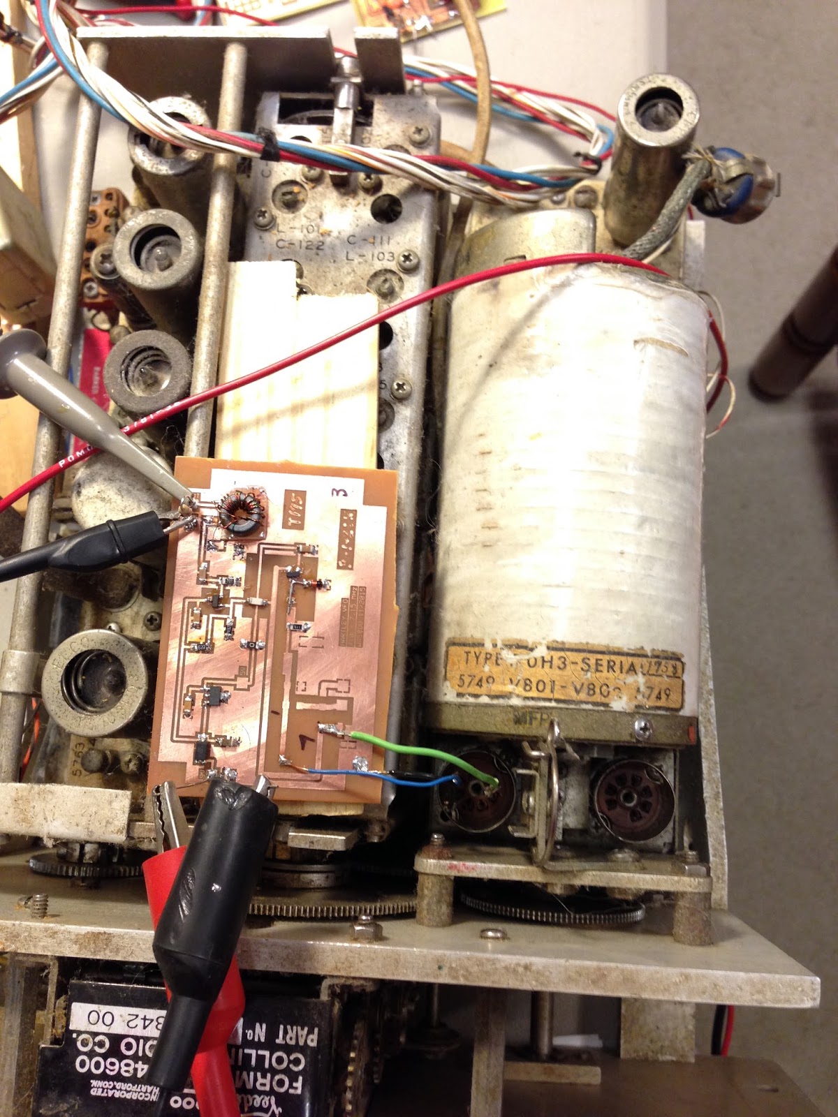
The magic is in that white soup can. It houses the frequency determining circuits. Between it and the front panel you see two tube sockets for the oscillator and buffer.
I found Army manuals for the thing on line and other resources in the form of a web page by John Seboldt K0JD giving lots of good information on doing just what I want to do:
http://www.seboldt.net/k0jd/t368vfo.html
That led to a good article on the subject "Transistorizing Surplus VFOs", QST February 1989, p 45.
The QST article used two dual-gate MOSFETs. K0JD used a JFET oscillator and DG MOSFET buffer. I fooled with that in LTspice but didn't like it so I used a JFET for the oscillator and a BJT (NPN) for the buffer as an emitter follower to give me a 50 ohm output and fairly decent looking sine wave.
It was essentially a Hartley I had built earlier on an SMT board with little SOT-23 active devices, SMT versions of the 2N4416A and 2N3904. I reused that board design although it's much larger than it needs to be since the frequency determining components aren't required.
As seen in the photo, mine is a temporary lash-up although I don't know if I'll ever do it up right. I didn't want to go through the mechanical details of removing the oscillator to get to the bottom of the tube sockets, so I just stuck wires into the correct pins from the top. It worked out well that the nodes I needed to access are accessible on the tube pins.
After getting it all hooked up I've done some checking on stability. It has gone two hours without moving a single Hertz and at other times might move one or two Hertz in a 30 minute period. Actually, I'm not sure my frequency counter is stable enough for this measurement.
I want to mention linearity too, but first I'll put in my schematic. Note that I didn't do any connections to the buffer's tube socket. And to the oscillator I just connected to the top of the tank, the coil tap, and ground.

I'm not an expert on military radio equipment, but with some of the stuff I've looked at it appears that no expense was spared in design or construction. Just first class.
This unit has a mechanical counter to indicate the frequency. I took readings at intervals of 100 from 1500 to 3000 and plotted them in Excel. The linearity is very impressive although with the vertical scale of the plot it appears a little better than actual. It has to deviate by several kHz from the straight line before you can see it. There's also an offset of about 110 kHz which I can fix after I figure out how to disengage the shaft from the counter and reset it.

That white covering over the soup can is a heater. I thought I might turn it on and get even better stability, but it turns out that the setpoint is 32F! So you can surmise that the stability results from careful selection of components with regard to their temperature coefficients and the heater is just to keep the unit within the range that they can handle.
One drawback is the frequency range of 1.5 to 3.0 MHz. You've got 160, but double it and you only add 80. You'd need to double again for 40. Or heterodyning would be another approach.
If I were going to use this thing "for real", I'd probably add another stage of amplification to get to +7 dBm or more.
Note that K0JD added a varactor offset tuning circuit. That could be necessary in some applications, but I didn't want to adversely affect stability at this point in my playing.
I haven't considered trying to make any of the multiplier stages functional with solid state components thus far.
OK, fun project. If you see one, pick it up and have some fun playing with it.
Nick, WA5BDU